| About TMSV | Visitor information | Our collections |
Current projects | Feature articles | Join TMSV | Useful links | TMSV news |
|
|||||||||
|
|||||||||
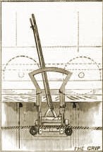
Cable trams: how they workThis article by Professor William Charles Kernot [1], appearing as ‘The Melbourne Tramways’, was first published in 1888 as a chapter within a book entitled Victoria and its Metropolis — Past and Present and reprinted in Cranston (1988) The Melbourne Cable Trams 1885-1940. The advantages that ensued from running vehicles on railways at an early date suggested the advisability of introducing rails and tramcars in the streets of large cities. The problem, however, was soon found to be a more complex and difficult one than that of making and working railways. The railway engineer is supreme and untrammelled in his domain and need consider nothing but the efficiency of his railway as a means of carrying his engines and carriages. The tramway engineer, on the contrary, is bound by many conflicting conditions. He must not only make his line so as to carry the tramcars, but what is a far more difficult problem, must so design it as to neither injure nor be injured by the vast number of vehicles, ranging from the light buggy of the medical man to the ponderous wagon or lorry, laden with many tons of material, which constantly use the same roadway. Many attempts to solve the problem were made before a satisfactory system of constructing the tramway was arrived at; while the question of the best method of propelling the cars has been, and still is, the subject of innumerable experiments, horses, steam motors, compressed-air engines, gas engines, and electricity have all had their turn, and even now there is considerable difference of opinion among experts [2]. Until recently the horse held its own in most European and American cities, with here and there a small locomotive as a somewhat feeble competitor. About ten years ago an extensive system of tramways with steam motors was introduced in Sydney, and at first the financial results were reported as exceedingly favourable. As time went on, however, the defects of this mode of transport became more and more apparent. The heavy locomotives proved very destructive to the tramway, which needed incessant repairs and frequent renewals, while the engines themselves, exposed as they were to the dust and mud of the street, required constant attention. Though the number of passengers was enormously large, the annual balance sheet showed very little return for the capital expended. Moreover, the snorting engines were an undeniable nuisance and danger in the streets, while the trams to any given locality were too few in number and too large in size to conduce to public convenience, which is best served by a constant succession of small handy vehicles. In Sydney the steam motor was tried on a most extensive scale, and was certainly not found satisfactory. Meanwhile a most interesting experiment was going on in San Francisco. A tram line was constructed to run up a hill too steep for horses or steam motors, and the cars were propelled by a wire rope passing along a tunnel underground, and the wire rope was powered by a stationary engine at one end. The cars, small, and comparatively numerous, were provided with a gripper, which may be described as a kind of iron hand which extends from the car, passes through a slit in the road, and grasps the moving cable beneath. When the gripper was tightened by the driver or gripman, the car was dragged along at the speed of the cable; when the gripper was slacked the car stopped. Thus the traffic was conducted up a very steep hill with the result that a suburb hitherto almost inaccessible was brought into close communication with the business part of the City, and the value of the property in it enormously enhanced. The success of the experiment was complete, though it must be admitted it was tried under very favourable circumstances, for the steepness of the grade not only prevented any other system of propulsion coming into competition but also, by almost completely stopping ordinary traffic, saved the tramway from the wear and tear due to heavy wagons passing across or along it. A few initial difficulties in points of practical detail having been overcome, the cable tram at once became a great success for hilly lines when other systems were at a disadvantage, and was speedily repeated in other hilly parts of San Francisco and also in New Zealand. But more was to follow. The excellent results obtained on steep grades led to it being tried on flatter roads, where ordinary traffic was considerable, and where horse trams constituted a formidable competitor. Then Chicago, a level city, took the system up, and so did Melbourne, which up to this time had been behind Adelaide and Sydney in tramways as it still is with respect to sewerage. Each cable tramway as it was constructed embodied the results of its predecessors and gave the opportunity of testing new ideas, and it is now alleged that the Melbourne system represents the most recent advances in this branch of engineering. Cable tramways, as existing in Melbourne, are most massively constructed, the consideration of economy in first cost being regarded as of little importance in the presence of that of durability and ease of working. Though the cars are relatively light [3], the rails are heavier than those used for the largest and swiftest locomotive, and are further solidly supported upon concrete foundations.
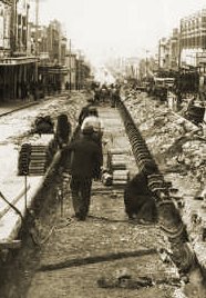
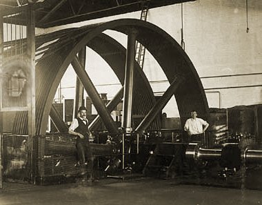
Midway between each pair of rails comes the tunnel or trough in which the cable works. This is constructed of concrete, and is large enough for a man to crawl along. The slit, or opening, for the gripper, is guarded by two steel lips, or slot pieces, which are supported at every three feet by yokes, which are steel rails bent in a sort of horseshoe shape and embedded in the concrete wall of the tunnel. The rails and slot pieces are kept at the proper distance apart by rods with adjusting screws, and the intervening space is filled up with wood blocks to the level of the heads of the rails. Such a road is, of course, very expensive, containing as much metal in the case of a double tramway as would make no less than six lines of fairly heavy railway, in addition to a very considerable quantity of concrete; but it is all necessary according to the tramway engineers, if the road is to be durable and satisfactory. The opening, or slit, down which the gripper passes is a most delicate and critical matter. If made in the least degree too wide, the wheels of the light buggies drop down it. If too narrow, the gripper scrapes and jams. To obtain the right width at first, and maintain it afterwards, is an object of the greatest solicitude. At first a good deal of difficulty arose from the expansion of the wood blocks closing the slit, but by tying the work together with bolts and inserting a line of elastic material between the blocks, and with other precautions, the trouble has been in great manner overcome, though now gangs of men are occasionally seen, especially in the small hours of the morning, removing blocks and adjusting the screws. In the tramway tunnels small pulleys of cast-iron, about nine inches in diameter, are placed at intervals of eleven yards, on which the cable rests. At curves, which are introduced as rarely as possible, large drums on vertical axles are used. All these are rendered accessible with iron frames and doors level with the street, and they are continually visited by men appointed to examine them and apply oil. At each terminus is a large pit roofed over with iron girders and plates, and containing a large iron wheel also known as a sheave, twelve feet in diameter, round which the rope passes. The engine houses are usually placed about the centre of the line, and are large and in many cases highly architectural structures, constituting very prominent features in the localities where they are found. In the street, in front of each engine-house, is a pit or chamber, containing a bewildering maze of huge pulleys. Entering one of them by a convenient passage or staircase, we find it brilliantly lit up with gas or electricity; we see cable passing in various directions, while over our heads the grippers of the cars pass, opening and releasing one cable, and closing upon another. As may be supposed, it is a matter of highest importance that the gripper should be opened at the right points, and a comparatively small error on the part of the gripman may lead to a great injury to the gripper, or, what is far worse, to the cable or pulleys. To aid the gripman as much as possible, white marble blocks [4] are inserted in the roadway, and illuminated in some cases by powerful lamps. The mode of actuating each cable is as follows. Two wheels, twelve feet in diameter, with grooves in their rims filled with hardwood, are caused to rotate in opposite directions by toothed wheels connected with them; the cable passes around the wheels in the form of a letter S, going three-fourths of the way around each wheel; it then runs away to a tightening wheel, supported on a carriage and urged by a heavy weight away from the other wheels; from this it returns, passed under the first-mentioned wheels without touching them, and then proceeds to the pit or chamber under the street. The tightening wheel travels along a race or railway fifty yards or more in length, and so takes up the variation in length of the cable due to stretching, expansion by heat, or other cause. The apparatus described above is driven by a pair of engines from 200 to 400 horsepower through the medium of rope gearing. A wheel of about ten foot diameter, driven by the engine, is connected to one 24 feet in diameter by a series of hemp ropes for the purpose of reducing the velocity of rotation. These huge wheels, weighing about fifty tons, form a most striking feature in a Melbourne tramway engine house. The engines themselves are horizontal and non-condensing, and work in pairs; the cylinders are from 20 to 40 inches in diameter, and from 40 to 48 inches stroke. The smaller ones make about sixty revolutions per minute; the larger about forty-five. They are all provided with sensitive governors and automatic expansion gear for the double purpose of economising steam and of enabling the engines instantly to accommodate themselves to the ever-varying demand for power due to the continual gripping and un-gripping of heavily laden cars. How great the variation is is [sic] clearly testified by the continual rising and falling of the governors and constant movement of the tightening pulley. Steam is supplied to the engines by a series of boilers working at a pressure of 90 to 100 pounds per square inch. These boilers are of two forms — the smaller are an American type known as Babcock and Wilcox, and consist of a multitude of small tubes containing water and surrounded by the flame and smoke from the furnace; the larger ones are large cylinders with flat ends, having corrugated furnace tubes, combustion chambers, and a series of small tubes, through which the flame returns, and which are surrounded by water, the whole arrangement corresponding closely with those adopted on almost all modern steamboats. The simple old-fashioned Cornish or Lancashire boiler for some reason has not found favour with the tramway engineers. The exhaust steam from the engine is used in a simple and effective way to heat the water supplied to the boilers, and so economise fuel as much as possible without the aid of a condenser, which latter appliance was inadmissible, the engine houses being almost always placed on or near the highest ground passed over by the line, and consequently far from the river or any other cheap water supply. The engine houses are provided with tall and handsome brick chimneys, 150 feet or more in height. These chimneys now form conspicuous features [5] in most landscapes about Melbourne. At first the smoke from them was a nuisance, but afterwards it greatly diminished and at present some of the engine houses set a most excellent example to private steam users in the way of smoke prevention. The care, repair, and renewal of the cables are questions of most vital importance. The cost of the cables is so great, and their life, if they are not properly treated, so short, that no precaution is omitted that can conduce their well-being. They consist of six strands each, composed of a number of steel wires. These strands are laid spirally around a hemp core. The cable is stored at first on a huge reel, and from this taken down into the tunnel. The operation of threading the cable in the first instance is a very interesting one, the rope being dragged through by a hook attached to a dummy or small car which is drawn by a team of from twenty to thirty horses. This operation, once performed, rarely needs repeating, as at each subsequent renewal the rope is drawn through by the old one. When the cable is threaded the operation of splicing takes place. This is a most delicate and important matter, and is performed by an experienced cableman. The splice is about 60 feet long, and is so neatly made that it requires the closest scrutiny to detect it. This is necessary in order that it may run freely through the grippers and over the pulleys. The cable is kept well coated with an elastic composition, made of tar and other materials boiled together and allowed to drip slowly from a vessel under which the cable passes. When well coated, it presents the appearance of a smooth black cylinder about an inch in diameter. If the coating be absent, wholly or partially, then the cable runs harshly over the wheels, and very rapid wear both of the wheels and cable ensues. The cable is liable to be greatly injured if the gripper is not released at the proper point. A common result of such a mistake is that one strand is broken and torn away from the rest, and as the cable moves on, this broken strand unwinds and forms a huge entanglement in the tunnel. In order that such an undesirable result may take place to as small as extent as possible, telegraphic communication is made from various points on the route to the engine-house. In the event of any occurrence rendering it necessary to stop the cable, the conductor of the car opens a little box attached to a telegraph pole near at hand, and presses a knob. This causes a gong to sound in the engine-house, and the engine driver at once turns off the steam and applies a powerful brake, so stopping all machinery as rapidly as possible. In the absence of such a means of communication hundreds or thousands of feet of cable might be destroyed before the engineman knew that anything was wrong. When the cable has been in any way injured, the first thing is to carefully bring the injured part round to the engine-house, where it may be repaired or cut out altogether. As under such circumstances traffic is stopped, the repairing has to be done with extreme rapidity, and the speed and skill of the repairers are taxed to the utmost. When one tramway crosses another, as frequently occurs in the Melbourne system, one cable must pass beneath the other. The cars attached to the lower cable drop it before coming to the crossing place, run across the other tramway by momentum, aided sometimes by a slightly falling grade and pick up on the other side in the same way as they drop one cable and pick up another when passing an engine-house. This operation is a rather delicate one, and in the hands of a novice a mistake might easily occur and the cable be injured. So expert, however, do the gripmen become by constant practice that they pass over these square crossings without the slightest hesitation or trouble.
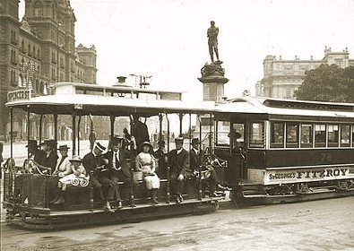
The cars are small, pleasing in appearance, and very convenient. They run in pairs. The forward one carries the gripping apparatus [6] in the centre, while all around are seats. It is roofed above, but otherwise open, and is very pleasant in fine weather. The second car or saloon has no gripper, but is towed along by the first car which is known as the dummy. This car is larger than the dummy, and is closed in, having doors and windows. It is intended for ladies, children, old people and non-smokers, smoking being allowed on the dummy. In fine warm weather, the dummy will often be quite full, and the closed car empty or nearly so; while under the opposite circumstances the gripman will have the dummy all to himself, the passengers seeking the comfort of the closed car. The system, as a whole, is a very satisfactory one, convenient, free from smell, smoke, or other nuisance, and neat in appearance. The only objections that can be urged are; firstly, its great prime cost, owing to the massive and complicated construction needed; secondly, its unsuitability to small traffic, as it would cost nearly as much to run two cars as twenty on any of the Melbourne lines; and thirdly, the liability of a large system consisting of several miles of tramway, carrying thirty cars, being brought to an absolute stop by a slight accident or mistake on the part of a single gripman. The first two objections have little force in a busy, wealthy, and populous city, while the third is felt less every day as the gripmen become more expert in their work. Further reading Buckley, J.R. (1975) History of Tramways from Horse to Rapid Transit,
David & Charles Footnotes
[1] William Charles Kernot (BA 1865, MA 1866, Certificate of Engineering, MCE) was born in Rochford, Essex, England on 16 June 1845. When he was six he migrated with his family to Australia and settled in Geelong. He was admitted to the University of Melbourne aged 15, studying civil engineering, becoming the University’s first engineering graduate. On graduating, he worked for a number of Government bodies including the Victorian Department of Mines and Water Supply Office, whilst lecturing part-time at his alma mater during 1866-75. From 1875 he expanded his lecturing commitment to the University of Melbourne whilst undertaking consulting work. Kernot was Australia’s first Professor of Engineering, University of Melbourne 1883-1909, was President of the Victorian Institution of Engineers, the Victorian Institute of Surveyors and the Royal Society of Victoria from 1885 to 1900. He was commemorated by the Kernot Medal for distinguished engineering achievement in Australia and three scholarships at the University of Melbourne. During the period 1885-93 Kernot consulted to the Victorian Government on engineering matters regarding the Melbourne cable tramway system. He died on 14 March 1909, having never married. [2] As this article was being written in 1887, Frank Sprague was perfecting the form of the modern electric tramway in Richmond, Virginia. This development was soon to sweep the cable tram aside. [3] A standard Melbourne cable tram dummy and trailer set weighed just over 5 tonnes empty, with a capacity of 54 passengers. [4] Marble strips (each about 4 inches wide) embedded transversely in the roadway between the rails were used to indicate to gripmen the required action for proper use of the grip mechanism. The signals were as follows:
[5] Although several cable tram engine houses have survived the closing of the Melbourne cable tram system, all the chimneys were demolished. [6] Colloquially known as the grip.
|
![]() Last
updated 1
August 2005.
Last
updated 1
August 2005.
![]() Footnotes
copyright © Russell
Jones 2005. Reproduced with permission.
Footnotes
copyright © Russell
Jones 2005. Reproduced with permission.