| About TMSV | Visitor information | Our collections |
Current projects | Feature articles | Join TMSV | Useful links | TMSV news |
|
|||||||||
|
|||||||||
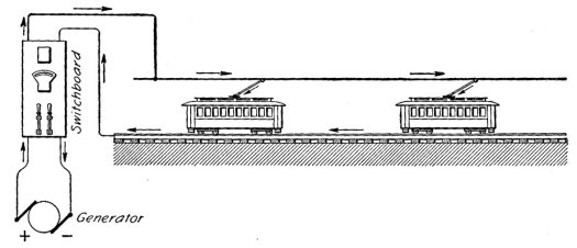
Electric trams: how they workThe electric tram is one of the few technologies perfected in the nineteenth century that survives essentially unchanged into the twenty-first, so that a tramcar built in the 1890s can run on a modern tramway. Modern tramcars still rely on the design principles established by Frank J. Sprague in Richmond, Virginia USA, in 1887. These essentials consist of:
Over the years various refinements have been made, such as replacement of series-parallel controllers with modern solid state control systems, and the substitution of trolley poles with pantographs. However, in the majority of tramways the electricity supply is still between 600 and 750 volts DC [1].
All the tramcars at the Bylands Tramway Heritage Centre built prior to 1956 share the same basic driver’s controls. On the left of the cab is the controller, in the centre of the cab is the hand-operated air brake valve, and on the right hand side of the cab is the handbrake wheel. In addition, there are two foot-operated buttons on the floor to the right of the controller — the gong button and the sand button. Cars fitted with air-operated doors (sliding or folding) have a hand-operated door valve to the right of the air brake valve. The ‘dugga-dugga’ noise heard from time to time on heritage tramcars puzzles many tram passengers. This is actually the air compressor pumping up the air reservoir when it falls below 60 psi, switching off when the pressure reaches 70 psi through the means of a pressure-operated switch. The reservoir supplies the compressed air to operate the brakes and doors. There are two handles on the top of the controller — the reversing switch and the controller handle. The reversing switch has a removable key that can be inserted or removed only when the switch is in its central ‘off’ position, which also locks the controller handle in the off position. The reversing switch has two ‘on’ positions — forward sets the tram to move forward, and back will set the tram to reverse. If the full traction voltage is applied to the motors from rest, they will overheat, short circuit and catch fire. This is hardly a desirable outcome, so a method had to be devised to avoid this from happening. The solution was to increase the voltage applied in a number of discrete incremental steps. The controller is basically a large rotary switch, similar in function to a ceiling fan switch. Early tramcars were fitted with controllers with about eight switch positions (called notches), although this varied from design to design. The controller is used to regulate the traction voltage to the motors, of which there will be either two or four on a traditional style tramcar, depending on the tramcar design.
On the fourth notch, there are no resistances in circuit, so the full 600 volts is across the motors. This means that there is about 300 volts across each motor. This notch is known as the full series notch. The next notch to be cut in is the first parallel notch, for which the motors are wired in parallel. When this notch is selected, passengers will note a distinct change in motor noise to series operation, and the rate of acceleration will be increased. However, in the first parallel notch, resistances are again placed in circuit, so that each motor does not receive the full 600 volts. Again, as the motors pick up speed, the driver will select the additional notches as for the series notches, progressively cutting resistances out of circuit on each notch, until the last notch is reached. This is known as full parallel, there are no resistances in circuit, and the full traction voltage of 600 volts is applied across each motor. Once the tram has reached the desired cruising speed, the driver will return the controller to the off position [3], allowing the tram to coast without power. This practice reduces power consumption as well as reducing heat build up in the motors, saving wear and tear. It should be noted that if the driver moves the controller down a notch, the power supply to the motors will drop out. The driver must return the controller to the off position before power can be reapplied to the motors. A tram driver should attempt to reach the full series or full parallel notches as quickly as possible, as otherwise power is wasted heating up the resistances. If the resistances get too hot, there is always the possibility that they will catch fire — an undesirable outcome! If the driver notches up too quickly, the motors will draw too much current and the line breaker will interrupt the supply in order to prevent damage to the motors. Another undesirable outcome is putting the traction motors into an ‘over-run’ condition — in other words exceed the maximum design speed of the motors. This is usually encountered when running downhill with power on. If it occurs, the motors are usually damaged and will require rewinding — a very expensive exercise. The real skill in driving heritage tramcars is in stopping them. The normal service brake is the airbrake, of which there are two types used on Melbourne trams — manual-lap and self-lap. The M&MTB had a progressive program to upgrade its tramcars from the 1930s onwards from manual-lap to self-lap, with all new tramcars past that date being built with self-lap brake valves. Manual-lap brake valves require the driver to manually control the amount of air admitted to the brake cylinders, whereas the self-lap valve admits a fixed amount of air according to the position of the brake handle, so that the brake valve acts like a progressive brake — similar to a motor car, where how quickly you stop depends on how hard you depress the brake pedal. Most of the tramcars in the TMSV collection are fitted with self-lap brakes, which don't require quite as much skill to use as manual-lap brakes. One of the problems faced by trams under heavy braking, particularly when the rails are greasy, is the possibility of the wheels locking up and the tram skidding, which is to be avoided at all costs. The immediate issue is that skidding trams, like cars, take longer to bring to a halt, but there is a longer term problem caused by trams skidding — wheel flats. Basically when a tram wheel locks up under brakes, the rail grinds a small flat section on the wheel surface. The result is a reduction in life of the wheel and a decrease in braking efficiency, as well as a noisy wheel. This can only be fixed by having the wheel returned to a round profile by wheel grinder at the depot or the wheel lathe at the workshops. The answer to this problem is the use of sand to increase the friction coefficient of the steel wheel on steel rail, reducing the tendency of the wheels to lock up under braking. The driver applies the sand to the rail head by pushing the floor mounted sand button with this foot, causing compressed air to blow sand on to the rail through pipes from the sand boxes mounted on the tram. This is why there is usually sand in the rail groove at tram stops, and why trams often seem to brake in a cloud of dust. As at the time of writing (January 2007), only two of the TMSV’s
tramcars — X 217 and And yes, heritage tram drivers do prefer to drive standing up. Bibliography Buckley, J.R. (1975) History of Tramways from Horse to Rapid Transit,
David & Charles Footnotes[1] Melbourne’s traction voltage has increased due to the heavier demands of new tramcar designs, so that the voltage is generally between 660-700V DC, depending on the location in the network. The Bylands tramway still operates at 600V DC. [2] Known as cutting a notch, or notching up.
|
![]() Last
updated 15
January 2007.
Last
updated 15
January 2007.
![]() Content
copyright © Russell
Jones 2007. Reproduced with permission.
Content
copyright © Russell
Jones 2007. Reproduced with permission.